Page 14 - 태화트랜스
P. 14

Protection Purpose Precision Current Transformers


                Model & Specification
                                                                          f=50Hz, Rb=1 n, PF=1.0, unit : percent / minute
                          Current   DCR       Im       Im       Im        Rnv          Pnv        Phase
                 Model No
                           Ratio    士6%     Rb=1Ω    Rb=20Ω Rb=500Ω 1-20A, Rb=0    1-20A, Rb=0   Shift at 1V
                 TC140V/L  1000:1   34Ω      125A      82A      8A        1.2%         10'          88'
                 TC141V/L  1000:1   29Ω      250A     156A      14A       0.7%         60'          65'
                 TC142V/L  1000:1   19Ω      460A     230A      17A       2.2%         90'          34'
                 TC143V/L  4000:1   154Ω     940A     840A     210A       1.5%         86'          13'
                                                                          f=50Hz, Rb=1 n, PF=1.0, unit : percent / minute
                          Current   DCR       Im       Im       Im        Rnv          Pnv        Phase
                 Model No
                           Ratio    士6%     Rb=1Ω    Rb=20Ω Rb=500Ω 1-20A, Rb=0    1-20A, Rb=0   Shift at 1V
                 TC172V/L  2500:1   129Ω     210A     170A      45A       1.0%         55'          62'
                 TC173V/L  2500:1   187Ω     260A     240A      70A       1.2%         62'          28'
                 TC174V/L  2500:1   51Ω     〉1000A    790A     100A       1.3%         100'         13'
                 TC175V/L  2000:1   26Ω     〉1000A    790A      67A       1.4%         95'          11'
                 Definition of Terms
                 Im : Max rated current Rnv : Nominal variation of ratio error at the mentioned primary current range Pnv : Nominal variation of phase
                 error at the mentioned primary current range Rb : Burden resistance PF : Power factor OCR : DC Resistance of secondary winding
                 Remark : The data of maximum current, ratio and phase error on 60Hz testing would be around 20% better than those of above
                 50Hz
                                                                          f=50Hz, Rb=1 n, PF=1.0, unit : percent / minute
                                                                                      lmax
                   Model No    Current Ratio  DCR(土6%)    Tolerance
                                                                        Rb=1Q       Rb=20Q       Rb=500Q
                     TC1PV       1000:1        62Ω                       54A          42A           5A
                     TC2V/L      1000:1        41Ω                       60A          44A           5A
                      TC3L       1000:1        33Ω          土3%          142A         95A           9A
                    TC4V/L /     1000:1        19Ω                       460A         230A         17A
                     TC5V        1000:1        12Ω                       660A         260A         16A
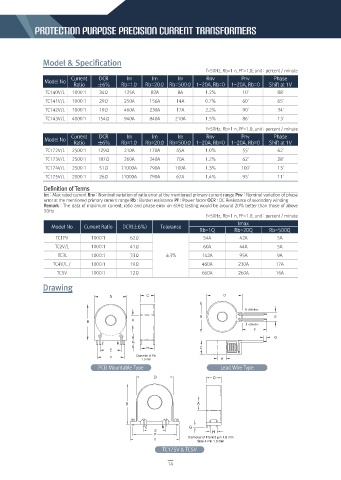
                Drawing


                                    PCB Mountable Type                         Lead Wire Type


                                                           TC175V & TC5V

                                                             14
   9   10   11   12   13   14   15   16   17   18   19